← All Chapters
Summary Note 6 / 7

Chapter 6 & 7 – GW Exploration, Well Design & Numericals

GWE Handwritten Notes

Page 59

Page 59
Transcription

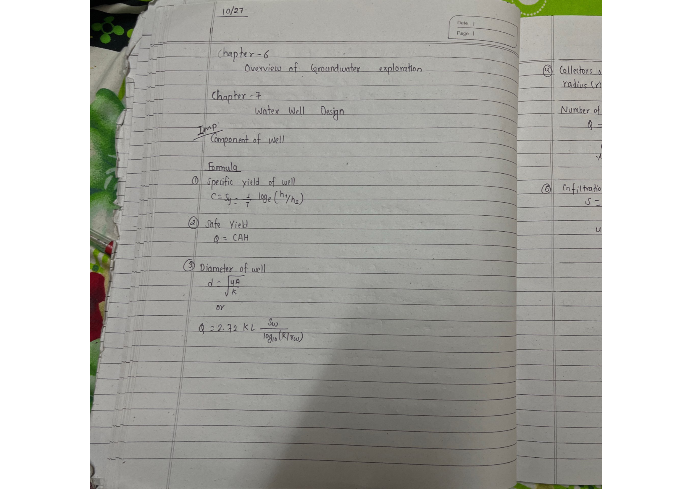
10/27

Chapter 6 – Overview of Groundwater Exploration

Chapter 7 – Water Well Design

Imp: Component of well

Ground Surface ← Casing Pump Grout Seal → SWL Aquifer ← Screen ← Gravel Pack ← Sump
Fig: Components of a typical water well

Formulae

① Specific yield of well (recuperation test):

\[ C = S_y = \frac{1}{T}\ln\left(\frac{h_1}{h_2}\right) \]

② Safe Yield:

\[ Q = C \cdot A \cdot H \]

③ Diameter of well:

\[ d = \sqrt{\frac{4A}{\pi}} \]

Dupuit formula:

\[ Q = 2.72\,K\,L \times \frac{S_w}{\log_{10}(R/r_w)} \]
Page 60

Page 60
Transcription

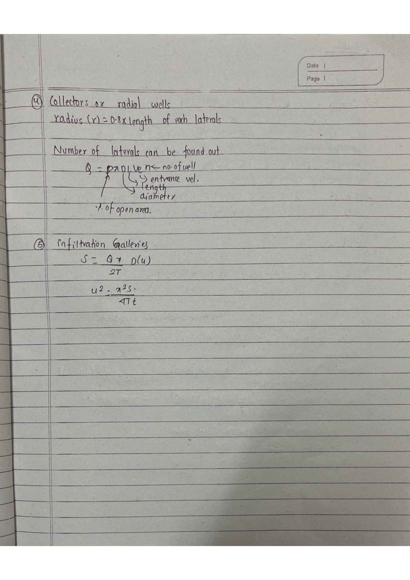
④ Collectors or radial wells:

radius (r) = 0.8 × length of each lateral

\[ Q = p\,\pi\,D\,L\,V_e\,n \]

where p = % open area, D = diameter, L = length, Ve = entrance velocity, n = no. of laterals

⑤ Infiltration Galleries:

\[ S = \frac{Q}{2T}\;p(u) \quad;\quad u^2 = \frac{r^2 S}{4Tt} \]

Page 61

Page 61
Transcription

Date: 10/28

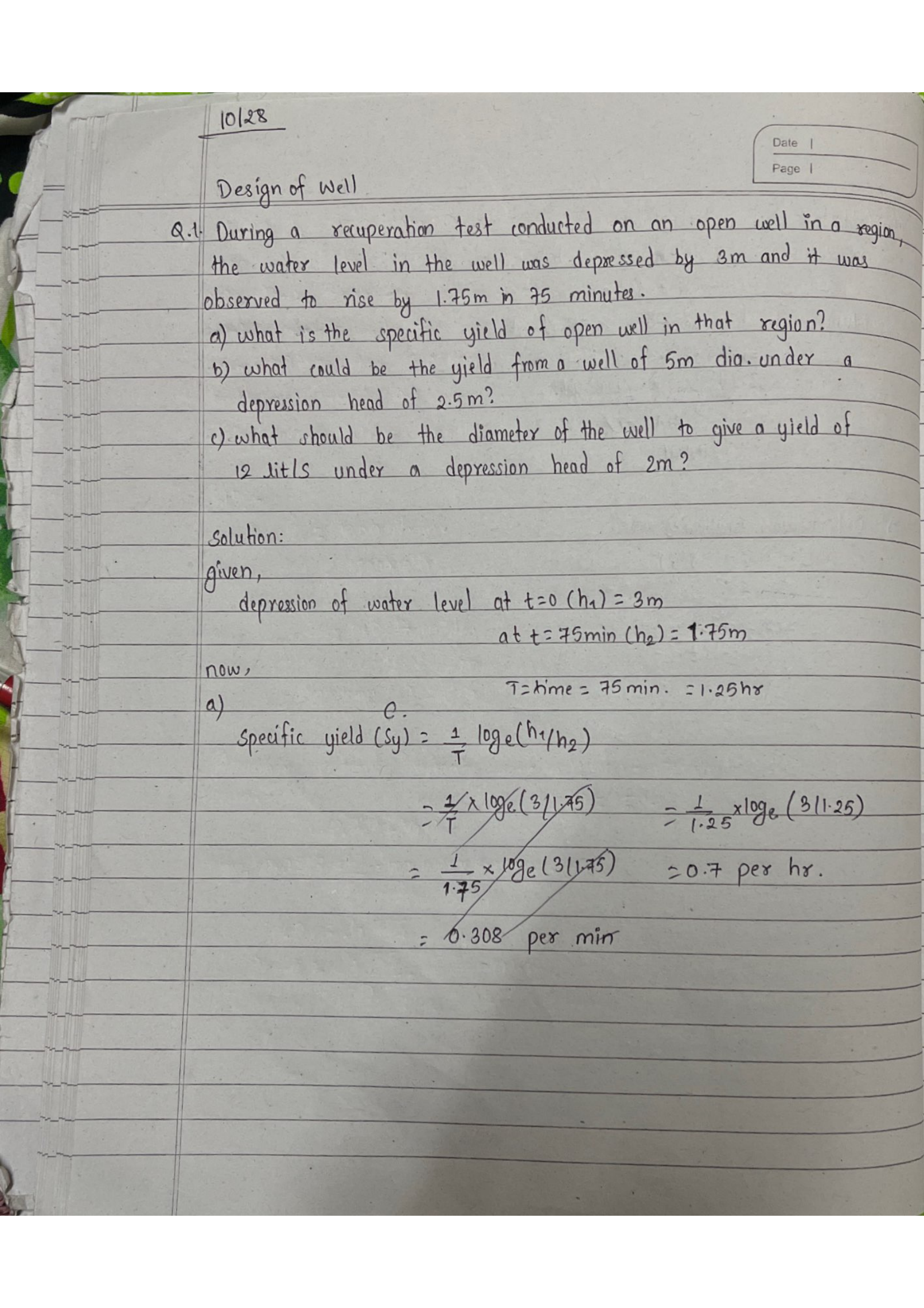
Numerical 1 – Recuperation Test (Open Well)

Q. Water depressed 3m, rose 1.75m in 75 min. a) Sy? b) Yield from 5m dia. well, H=2.5m? c) Diameter for Q=12 l/s, H=2m?

SWL h₁ = 3 m (initial) h₂ = 1.25 m (after T) rise = 1.75 m h₁ h₂ T = 75 min
Fig: Recuperation test — water level recovery in open well

Solution:

Step 1 — Identify h1 and h2 (depths below SWL):

  • h1 = 3 m (initial depression below SWL)
  • Water rose 1.75 m → h2 = 3 − 1.75 = 1.25 m

T = 75 min = 75/60 = 1.25 hr

a) Specific yield of well:

\[ C = S_y = \frac{1}{T}\ln\left(\frac{h_1}{h_2}\right) = \frac{1}{1.25}\ln\left(\frac{3}{1.25}\right) = 0.8 \times 0.8755 = \boxed{0.7\;\text{per hr}} \]

Page 62

Page 62
Transcription

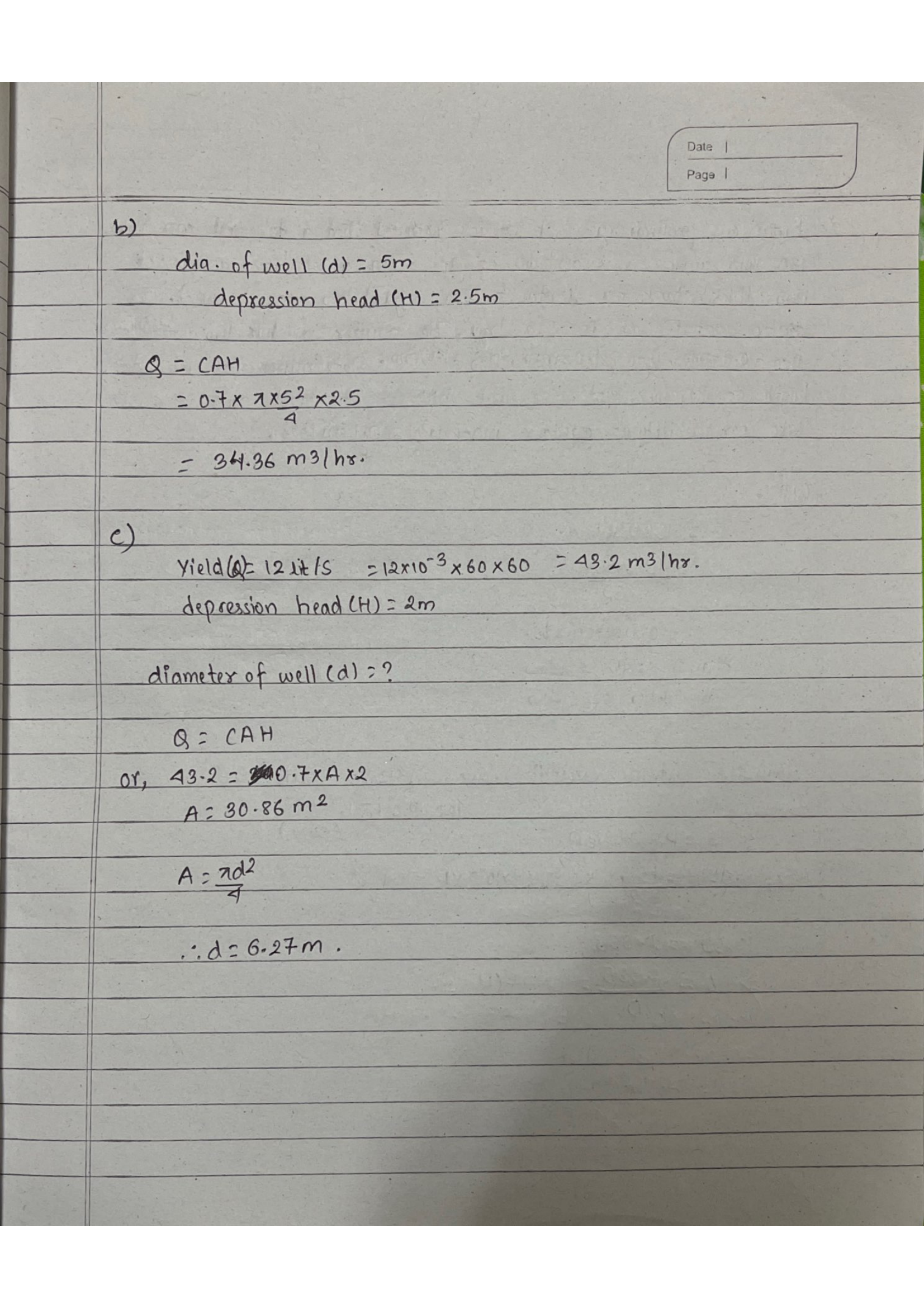
b) Yield from well (d=5 m, H=2.5 m):

Step 2 — Apply yield formula Q = C · A · H:

  • Cross-sectional area A = πd²/4 = π×5²/4 = 19.635 m²
  • Depression head H = 2.5 m (working head under pumping)
\[ Q = C \cdot A \cdot H = 0.7 \times 19.635 \times 2.5 = \boxed{34.36 \text{ m}^3\text{/hr}} \]

c) Diameter for Q=12 l/s, H=2 m:

Step 3 — Rearrange for area then diameter:

  • Q = 12 l/s = 12×3600/1000 = 43.2 m³/hr
  • A = Q/(C×H) = 43.2/(0.7×2) = 30.86 m²
\[ d = \sqrt{\frac{4A}{\pi}} = \sqrt{\frac{4 \times 30.86}{\pi}} = \boxed{6.27 \text{ m}} \]

Page 63

Page 63
Transcription

Numerical 2 – Tubewell Design

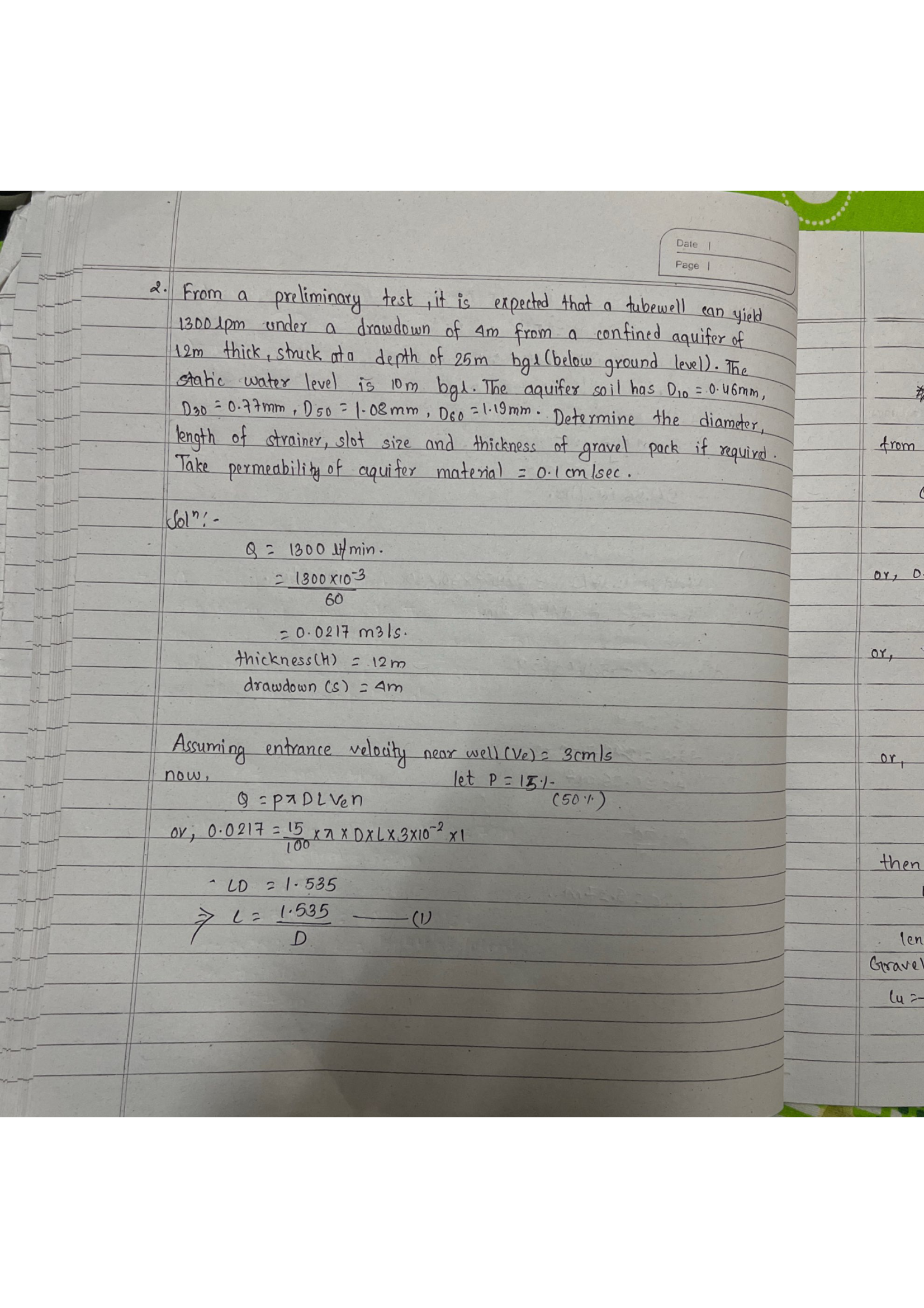
Q. Q=1300 lpm, confined 12m thick at 25m BGL, SWL=10m, Sw=4m. D10=0.46mm, D30=0.77mm, D50=1.08mm, D60=1.19mm. K=0.1cm/s. Find diameter, strainer length, slot size, gravel pack.

Solution:

Step 1 — Convert units and establish design parameters:

  • Q = 1300 lpm = 1300/(60×1000) = 0.0217 m³/s
  • Entrance velocity Ve = 3 cm/s = 0.03 m/s (recommended for confined)
  • Percent open area P = 15% (strainer open area fraction)
  • K = 0.1 cm/s = 0.001 m/s

Step 2 — From strainer intake formula Q = P·π·D·L·Ve :

\[ Q = P\,\pi\,D\,L\,V_e \quad\Rightarrow\quad 0.0217 = 0.15 \times \pi \times D \times L \times 0.03 \]

⇒ D·L = 1.535 ⇒ L = 1.535/D …(1)

Page 64

Page 64
Transcription

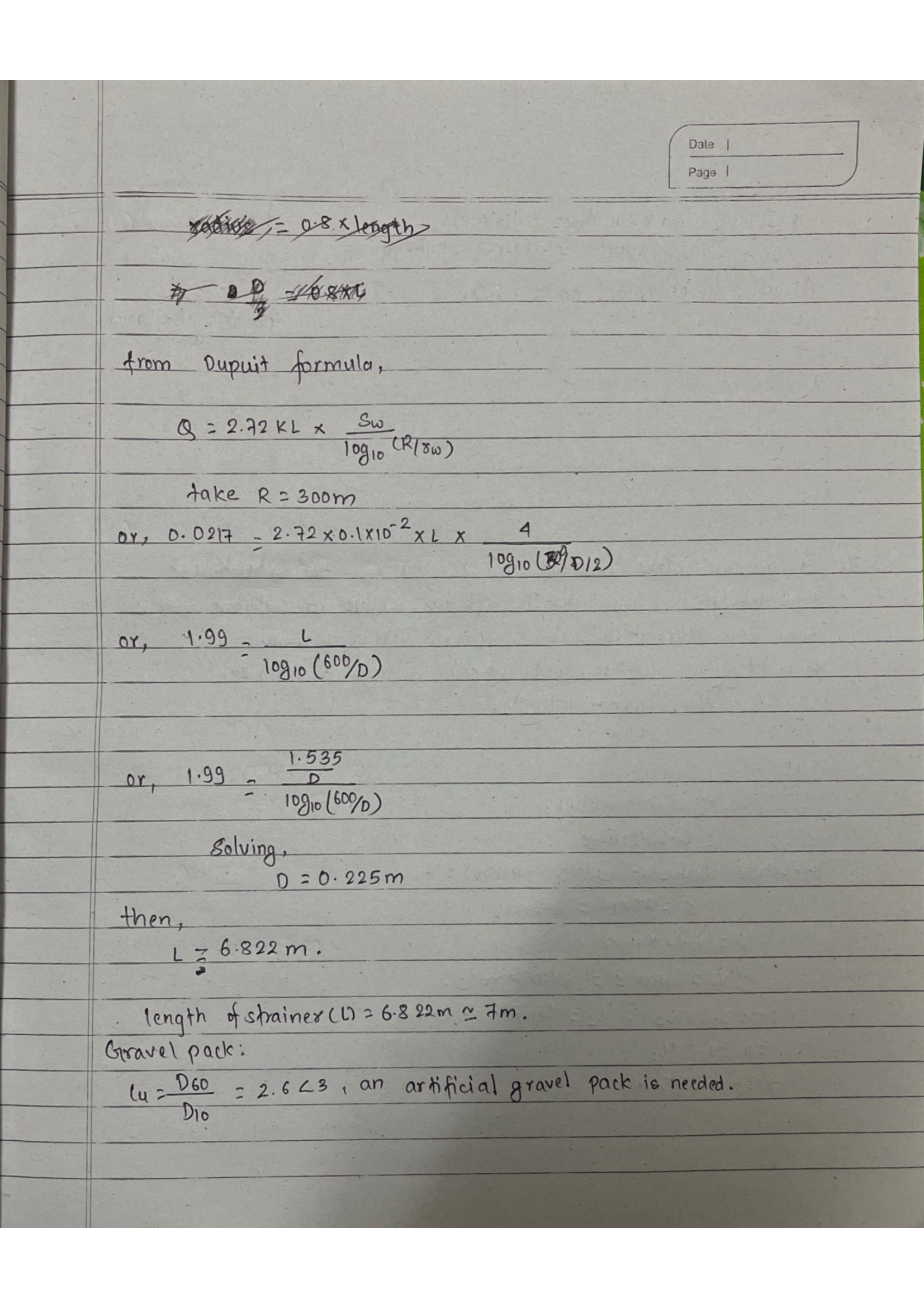
Step 3 — From Dupuit’s formula (R=300 m assumed):

\[ Q = \frac{2.72\,K\,L\,S_w}{\log_{10}\!\left(\frac{R}{r_w}\right)} \quad\Rightarrow\quad 0.0217 = \frac{2.72 \times 0.001 \times L \times 4}{\log_{10}(300/(D/2))} \]

Step 4 — Substitute L = 1.535/D from Eq.(1) and solve simultaneously:

  • Trial & error or graphical: intersection gives
\[ D = \boxed{0.225 \text{ m}} \quad;\quad L = 1.535/0.225 \approx \boxed{7 \text{ m}} \]

Step 5 — Check if natural gravel pack or artificial needed:

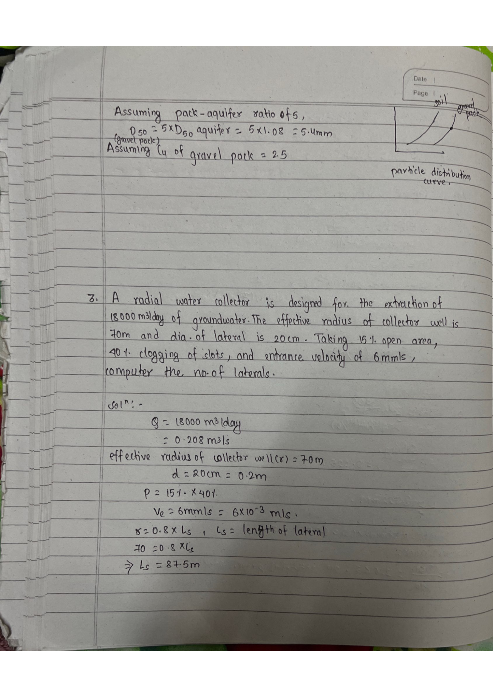
\[ C_u = \frac{D_{60}}{D_{10}} = \frac{1.19}{0.46} = 2.6 < 3 \quad\Rightarrow\quad \text{Uniform aquifer} \Rightarrow \text{artificial gravel pack needed} \]

Rule: If Cu < 3, aquifer is too uniform — needs artificial gravel pack to prevent sand entry.

Page 65

Page 65
Transcription

Step 6 — Design the gravel pack:

  • Pack-aquifer ratio = 5: D50(gravel) = 5 × D50(aquifer) = 5 × 1.08 = 5.4 mm
  • Cu of gravel pack ≤ 2.5: D10(pack) = 5.4/2.5 = 2.16 mm
  • Slot size = D10(pack) = 2.16 mm

Numerical 3 – Radial Collector Well

Q. Q=18,000 m³/day, effective radius=70m, lateral dia.=20cm, 15% open area, 40% clogging, Ve=6mm/s. No. of laterals?

R=70m Caisson Lateral d=20cm
Fig: Radial collector well — plan view with laterals

Solution:

Step 1 — Convert given data:

  • Q = 18,000 m³/day = 18000/86400 = 0.208 m³/s
  • Ve = 6 mm/s = 0.006 m/s
  • Lateral diameter D = 20 cm = 0.2 m

Step 2 — Find effective screen length (intake from inner 80% only):

Ls = Reff / 0.8 = 70/0.8 = 87.5 m per lateral

Page 66

Page 66
Transcription

Step 3 — Compute number of laterals (accounting for 40% clogging):

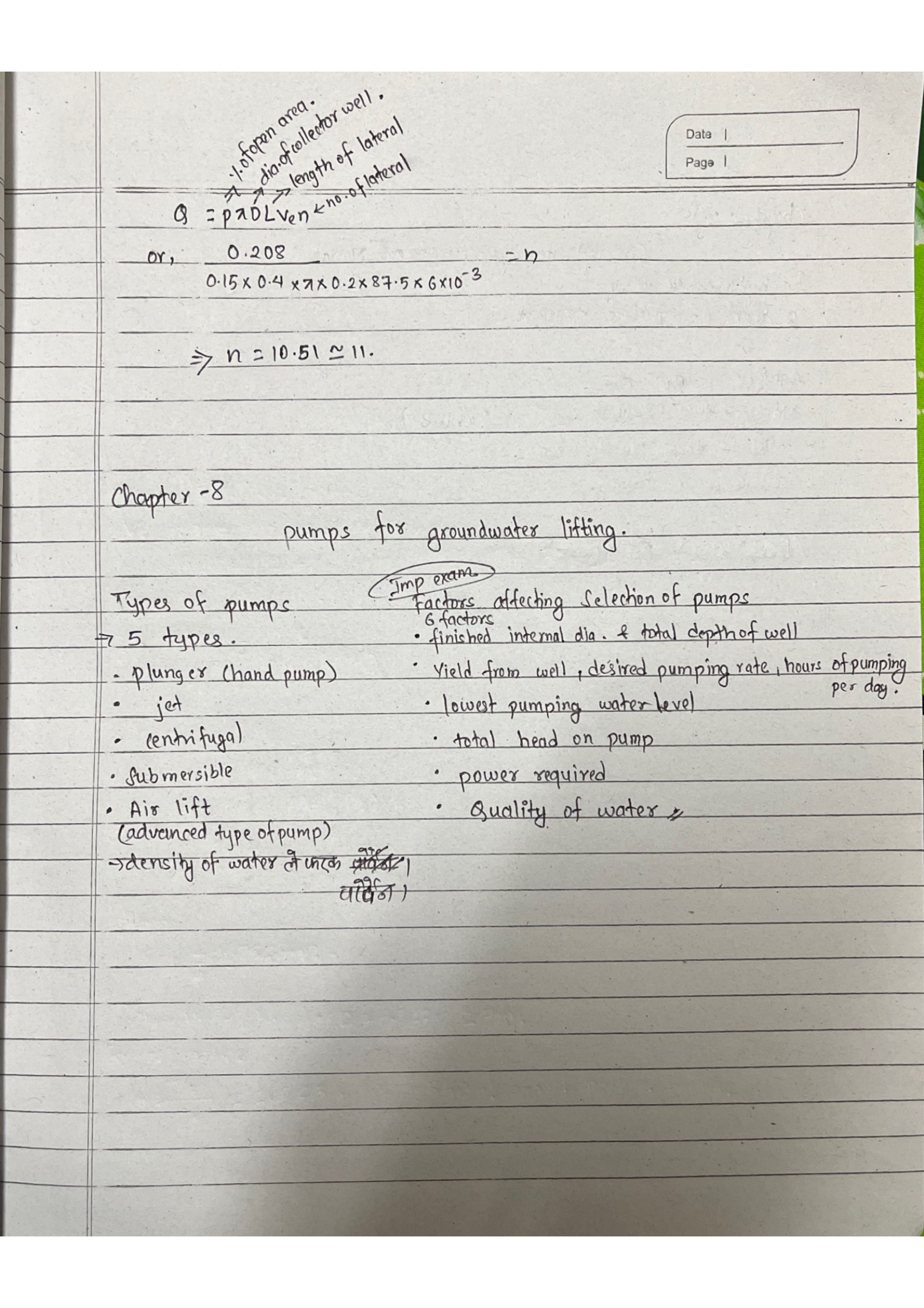
\[ n = \frac{Q}{P \times (1-\text{clogging}) \times \pi D \times L_s \times V_e} = \frac{0.208}{0.15 \times 0.60 \times \pi \times 0.2 \times 87.5 \times 0.006} \approx \boxed{11 \text{ laterals}} \]

Note: The factor (1−0.40) = 0.60 accounts for 40% clogging of the strainer open area.


Chapter 8 – Pumps for Groundwater Lifting

(Important for exam)

Types of Pumps (5):

  1. Plunger pump (hand pump)
  2. Jet pump
  3. Centrifugal pump
  4. Submersible pump
  5. Air lift pump

Factors Affecting Selection (6):

  1. Finished internal dia. & total depth of well
  2. Yield from well, desired pumping rate, hours of pumping per day
  3. Lowest pumping water level
  4. Total head on pump
  5. Power required
  6. Quality of water