4.1 Flexural Behaviour of Reinforced Concrete
Bending is resisted by an internal compression force and an equal tensile force separated by a lever arm. In a sagging beam the top is normally in compression and the bottom in tension; near a continuous support under hogging moment the roles reverse. Reinforcement must follow the tension face of the actual moment envelope, not a rule that all main bars belong at the bottom.
At low loads the section is nearly elastic and uncracked. After flexural cracking, steel carries the tension across cracks and stiffness reduces. As loading increases, a properly proportioned tension-controlled section develops large steel strain and rotation before concrete crushing. Brittle shear, bond, compression or joint failures must be prevented if that flexural ductility is to develop.
Equilibrium, Compatibility and Material Law
- Equilibrium: for pure bending without axial load, C = T and M = Cz = Tz.
- Compatibility: plane sections remain plane. At a flexural compression strain of 0.0035, εst = 0.0035(d − xu)/xu.
- Material response: obtain concrete and steel stresses from the relevant design curves. Do not assume a compression bar develops 0.87fy without checking its strain.
The IS 456 parabolic-rectangular concrete distribution has resultant C = 0.36fckbxu at 0.42xu from the compression face. The peak stress 0.446fck is not the average stress over xu. For a section satisfying the tensile-strain requirement, T = 0.87fyAst and z = d − 0.42xu.
Complete Singly Reinforced Design Procedure
- Establish the effective span, support conditions and factored bending-moment envelope. Add beam self-weight only when excluded from the stated loading.
- Select width, overall depth, exposure cover and a trial bar arrangement. Derive the actual effective depth to the centroid of all tension layers.
- Calculate xu,max for the steel grade and Mu,lim = 0.36fckbxu,max(d − 0.42xu,max).
- When Mu ≤ Mu,lim, solve Mu = 0.36fckbxu(d − 0.42xu) for its smaller physical root, then obtain Ast = 0.36fckbxu/(0.87fy).
- Apply minimum steel Ast,min = 0.85bd/fy and ordinary maximum tension steel 0.04bD. Select actual bars, then recheck xu and capacity using the provided area.
- Check that the bars physically fit with the required clear horizontal and vertical spacing. A second layer reduces effective depth and changes capacity.
- Complete shear, anchorage, curtailment, serviceability and detailing checks. A flexural calculation alone is not a complete beam design.
When the moment is too large: a doubly reinforced solution adds a compression-steel couple; a deeper or wider section may be more practical. The dimensions given in an exam question should not silently be changed. If an alternative size is proposed, distinguish it from a solution for the specified section.
Doubly Reinforced Design and the Displaced Concrete Correction
At the code-limiting neutral axis, separate Mu into Mu,lim and an additional moment M2. Compression steel at depth d′ has strain εsc = 0.0035(1 − d′/xu,max). Read fsc from the appropriate design curve. The concrete stress at that same level is fcc; it equals the plateau stress only if the local concrete strain has reached 0.002.
Asc = M2/[(fsc − fcc)(d − d′)]
Ast1 = 0.36fckbxu,max/(0.87fy)
Ast2 = M2/[0.87fy(d − d′)]
Ast = Ast1 + Ast2
The subtraction fsc − fcc prevents counting both steel and the concrete displaced by it. After rounding to actual bars, re-establish equilibrium with the provided compression and tension steel; excess tension steel can move the neutral axis past its permitted limit. Keep compression bars laterally restrained by links.
4.2 Design of Rectangular Beams (Singly & Doubly Reinforced, LSM) 208120792074207320722071
PAST EXAM QUESTIONS:
- A simply supported reinforced-concrete beam has an effective span of 4 m and overall dimensions of 250 mm × 475 mm. It is subjected to a superimposed uniformly distributed load of 45 kN/m, excluding its self-weight, together with a point load of 75 kN at midspan. Design the beam for the limit state of collapse in flexure. Also check whether the beam is safe in deflection. Consider an effective cover of 45 mm, and use M25 concrete and TMT reinforcement. All the given loads are at service level. [10] (2079 Bhadra, Q1c) → also 6.3
- A beam of size 250 mm × 300 mm is simply supported on masonry walls 300 mm thick, 4 m apart, to support a live load of 8 kN/m and dead load of 10 kN/m (including self-weight). Design the beam in flexure. Use M20 concrete and Fe415 steel. [8] (2081 Bhadra, Q2a)
- A beam has a rectangular section 300 mm wide and 500 mm deep to the centre of its tensile reinforcement. It has to carry a dead load of 45 kN/m, excluding its self-weight, over a span of 7 m. Find the steel reinforcement required at the midspan section using the limit state method. Take the effective cover to the compression reinforcement as 40 mm. Use M20 concrete and Fe415 steel. [15] (2074 Chaitra, Q1b)
- A simply supported rectangular RCC beam of effective span 5.5 m and overall dimensions 230 mm × 550 mm is subjected to a superimposed load of 50 kN/m, excluding its self-weight. Design the beam for the limit state of collapse in flexure. Also check whether the beam is safe in deflection. Adopt mild exposure, use Fe415 steel and take effective cover to the bars as 50 mm. [14] (2072 Chaitra, Q1b) → also 6.3
- Design the reinforcement required for a simply supported rectangular beam with an effective span of 6 m. The beam carries a load of 8 kN/m from a slab 120 mm thick. Take the beam width as 250 mm and its overall depth as 450 mm. For the loading calculation, consider a live load of 5 kN/m, a floor-finish load of 3 kN/m and a partition-wall load of 10 kN/m. Use M20 concrete and Fe415 steel. [12] (2067 Ashadh, Q3b)
- A simply supported RCC beam of effective span 4.5 m is subjected to a superimposed load of 45 kN/m, excluding its self-weight, with a point load of 75 kN at midspan. Design the beam for the limit state of collapse in flexure. Also check whether the beam is safe in deflection. Consider an effective cover of 45 mm. Take M25 concrete and Fe415 steel bars. All the given loads are at service level. [8] (2082 Baishakh, Q2a)
- Describe the requirement of steel as reinforcement in RCC structures. Explain the moment of resistance of a doubly reinforced section. Derive the formula. [2+2+4] (2076 Chaitra, Q1a) → also 1.1
- Derive equations for the bending moment carrying capacity of a doubly-reinforced rectangular section using the assumptions for the working stress method given by IS 456:2000. [6] (2079 Bhadra, Q1b)
- Explain the design steps of a doubly reinforced section with neat sketches. [6] (2080 Baishakh, Q1c)
- A reinforced-concrete beam of size 300 mm × 500 mm is reinforced with 5 bars of 25 mm diameter in tension and 5 bars of 12 mm diameter in compression. Both groups of reinforcement have a clear cover of 25 mm. The effective span of the beam is 4.30 m. Find its moment of resistance at the ultimate state. Use M25 concrete and Fe415 steel. [12] (2071 Chaitra, Q4b)
- Find the ultimate moment resisting capacity of the beam shown in the figure. Use M20 concrete and Fe415 steel. The supplied T-section has flange width 2250 mm, flange thickness 150 mm, web width 250 mm, effective depth 450 mm and four 25 mm tension bars. [14] (2073 Shrawan, Q1b; flanged-beam question)
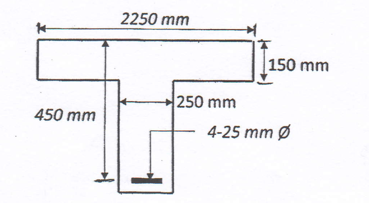
Figure supplied with 2073 Shrawan Q1b. The flange must be included in the analysis.
Q1. A simply supported reinforced-concrete beam has an effective span of 4 m and overall dimensions of 250 mm × 475 mm. It is subjected to a superimposed uniformly distributed load of 45 kN/m, excluding its self-weight, together with a point load of 75 kN at midspan. Design the beam for the limit state of collapse in flexure. Also check whether the beam is safe in deflection. Consider an effective cover of 45 mm, and use M25 concrete and TMT reinforcement. All the given loads are at service level. [10] (2079 Bhadra, Q1c)
Paper data: b = 250 mm, D = 475 mm, effective cover 45 mm, effective span 4 m, service UDL 45 kN/m excluding self-weight, central point load 75 kN and M25 concrete. Study assumptions: Fe500 for the unspecified TMT grade; compression-bar effective cover d′ = 45 mm.
1. Depth and loading. d = 475 − 45 = 430 mm. Do not subtract the bar radius again from an effective cover. Self-weight = 0.25 × 0.475 × 25 = 2.96875 kN/m. Mu = 1.5[(45 + 2.96875)4²/8 + 75(4)/4] = 256.406 kN·m.
2. Limiting section. xu,max = 0.46(430) = 197.8 mm and Mu,lim = 154.399 kN·m. Extra moment M2 = 102.008 kN·m, so compression reinforcement is required at the fixed depth.
3. Required steel. At the limiting axis, εsc = 0.0035(1 − 45/197.8); interpolation of the Fe500 design curve gives fsc approximately 410.58 MPa. The displaced concrete is on the plateau, fcc = 11.15 MPa. The two-couple equations give Asc = 663.34 mm² and Ast = 1632.20 mm².
4. Provided bars and verification. Select three 28 mm tension bars (1847.26 mm²) and two 25 mm compression bars (981.75 mm²). Re-solving force equilibrium using the provided areas and design steel curve gives xu = 183.97 mm < 197.8 mm, and MR = 296.01 kN·m > 256.41 kN·m. Check the nominal cover and link geometry that give the stated effective covers.
5. Deflection. L/d = 4000/430 = 9.302. The product of applicable modification factors must be at least 9.302/20 = 0.465. Read those factors using the actual steel and service stress, as shown in Chapter 6; comparing with the basic ratio alone is not a documented full check.
Study result Three 28 mm tension bars and two 25 mm compression bars satisfy the stated flexural check under the assumptions above. Complete shear, anchorage, bar fit and the explicit serviceability check for the final detail.
Q2. A beam of size 250 mm × 300 mm is simply supported on masonry walls 300 mm thick, 4 m apart, to support a live load of 8 kN/m and dead load of 10 kN/m (including self-weight). Design the beam in flexure. Use M20 concrete and Fe415 steel. [8] (2081 Bhadra, Q2a)
Given: b = 250 mm, D = 300 mm, wall width = 300 mm, walls 4 m apart, w = 8 + 10 = 18 kN/m (incl. self-wt), M20, Fe415, cover 40 (d = 260 mm). Required: flexural steel.
1. Resolve the span. Interpret "walls 4 m apart" as a 4.0 m clear span; adopt effective covers d′ = D − d = 40 mm. Then Leff = min(4.00 + 0.26, 4.30) = 4.26 m. If the examiner intends 4.0 m centre-to-centre, explicitly use the alternative 3.96 m effective span.
2. Demand and steel. Self-weight is already included in the stated dead load. Mu = 1.5(8 + 10)4.26²/8 = 61.248 kN·m. Mu,lim = 46.632 kN·m. At the fixed 250 × 300 mm size, the required areas are Ast = 806.20 mm² and Asc = 199.68 mm².
3. Verify actual bars. Provide three 20 mm tension bars (942.48 mm²) and two 16 mm compression bars (402.12 mm²). Compatible analysis gives xu = 115.46 mm < 124.8 mm and resistance 73.10 kN·m > 61.25 kN·m.
Study result Keep the specified section and use the verified doubly reinforced trial above, subject to bar fit and the remaining design checks. A larger alternative section would require recalculated self-weight, span and actions.
Q3. A beam has a rectangular section 300 mm wide and 500 mm deep to the centre of its tensile reinforcement. It has to carry a dead load of 45 kN/m, excluding its self-weight, over a span of 7 m. Find the steel reinforcement required at the midspan section using the limit state method. Take the effective cover to the compression reinforcement as 40 mm. Use M20 concrete and Fe415 steel. [15] (2074 Chaitra, Q1b)
Given: b = 300 mm, d = 500 mm, DL = 45 kN/m (excl. self-wt), L = 7 m, d′ = 40 mm, M20 (fck = 20), Fe415 (fy = 415). Required: mid-span steel.
1. Loading assumption. Take the 7 m span as effective and adopt D = 550 mm to accommodate the given d = 500 mm. Self-weight = 0.3 × 0.55 × 25 = 4.125 kN/m. Hence Mu = 1.5(45 + 4.125)7²/8 = 451.336 kN·m.
2. Required reinforcement. With xu,max = 240 mm, Mu,lim = 206.945 kN·m. At d′ = 40 mm, the compression-steel design stress is approximately 353.38 MPa. The two-couple equations give Ast = 2907.31 mm² and Asc = 1542.39 mm².
3. Trial bars and equilibrium. Four 32 mm tension bars provide 3216.99 mm²; six 20 mm compression bars provide 1884.96 mm². At the stated centroids, compatible analysis gives xu = 237.19 mm < 240 mm and capacity 503.74 kN·m. The six top bars are a congested single-layer choice: with effective cover 40 mm their approximate clear spacing is 24 mm, so aggregate size and placement must be selected consistently. If the bars need two layers, recompute the centroid and capacity.
Study result Required areas are 2907 mm² tension and 1543 mm² compression under the stated depth assumption. The trial cage passes the sectional calculation; its bar-fit and other member checks are mandatory.
Q4. A simply supported rectangular RCC beam of effective span 5.5 m and overall dimensions 230 mm × 550 mm is subjected to a superimposed load of 50 kN/m, excluding its self-weight. Design the beam for the limit state of collapse in flexure. Also check whether the beam is safe in deflection. Adopt mild exposure, use Fe415 steel and take effective cover to the bars as 50 mm. [14] (2072 Chaitra, Q1b)
Paper data: b = 230 mm, D = 550 mm, effective cover 50 mm, L = 5.5 m, Fe415 and mild exposure. Study assumptions: adopt M25, since the paper does not specify a concrete grade, and d′ = 50 mm.
1. Actions. d = 500 mm; self-weight = 3.1625 kN/m. Mu = 1.5(50 + 3.1625)5.5²/8 = 301.531 kN·m. Using 30 kN/m would substantially understate the demand.
2. Design. Mu,lim = 198.323 kN·m, so the specified section needs compression steel. With fsc approximately 352.12 MPa, the required areas are Ast = 2011.22 mm² and Asc = 672.65 mm².
3. Provided section. Two 36 mm tension bars give 2035.75 mm², and two 25 mm compression bars give 981.75 mm². Compatible equilibrium gives xu = 195.34 mm < 240 mm and MR = 317.80 kN·m > 301.53 kN·m. Check anchorage of the large tension bars and the detailed cover/link arrangement.
4. Serviceability. L/d = 11.0; the applicable modification-factor product must be at least 0.55. Record its chart value or calculate deflection explicitly before stating a pass.
Study result The adopted M25 doubly reinforced section passes the flexural check with two 36 mm tension bars and two 25 mm compression bars. M20 is another possible material assumption but requires a separate design.
Q5. Design the reinforcement required for a simply supported rectangular beam with an effective span of 6 m. The beam carries a load of 8 kN/m from a slab 120 mm thick. Take the beam width as 250 mm and its overall depth as 450 mm. For the loading calculation, consider a live load of 5 kN/m, a floor-finish load of 3 kN/m and a partition-wall load of 10 kN/m. Use M20 concrete and Fe415 steel. [12] (2067 Ashadh, Q3b)
Interpret the 8 kN/m slab load, 5 kN/m live load, 3 kN/m finish load and 10 kN/m partition load as separate service line loads. Do not multiply them by an additional tributary width. With a 250 × 450 mm beam, self-weight is 2.8125 kN/m. Assume d = 400 mm and d′ = 40 mm.
Mu = 1.5(8 + 5 + 3 + 10 + 2.8125)6²/8 = 194.484 kN·m
For M20/Fe415 the required areas are Ast = 1604.35 mm² and Asc = 680.80 mm². Three 28 mm tension bars and two 25 mm compression bars give xu = 183.71 mm < 192 mm and resistance 227.82 kN·m. The effective-cover assumptions and the separate member checks must be carried into the drawing.
Q6. A simply supported RCC beam of effective span 4.5 m is subjected to a superimposed load of 45 kN/m, excluding its self-weight, with a point load of 75 kN at midspan. Design the beam for the limit state of collapse in flexure. Also check whether the beam is safe in deflection. Consider an effective cover of 45 mm. Take M25 concrete and Fe415 steel bars. All the given loads are at service level. [8] (2082 Baishakh, Q2a)
The paper leaves beam size open. Select a 300 × 650 mm trial section, M25/Fe415, with the specified effective cover 45 mm, so d = 605 mm. Its self-weight is 4.875 kN/m. With 45 kN/m superimposed service load, 75 kN central point load and 4.5 m effective span:
Mu = 1.5[(45 + 4.875)4.5²/8 + 75(4.5)/4] = 315.932 kN·m
Solving the singly reinforced section gives Ast,required = 1721.43 mm². Three 28 mm bars provide 1847.26 mm². Their actual xu = 247.02 mm < 0.48d = 290.4 mm, with MR = 334.31 kN·m. L/d = 4500/605 = 7.438, requiring a serviceability modification-factor product of at least 0.372. Verify that factor, shear, anchorage and the final link arrangement.
Q7. Describe the requirement of steel as reinforcement in RCC structures. Explain the moment of resistance of a doubly reinforced section. Derive the formula. [2+2+4] (2076 Chaitra, Q1a)
Requirement of steel. Concrete has a comparatively low tensile strength and cracks under flexural tension. Longitudinal reinforcement carries tension across those cracks; compression reinforcement shares compressive force; stirrups resist diagonal tension and restrain longitudinal bars. Distributed reinforcement controls shrinkage and temperature cracks. Adequate bond, anchorage and confinement allow the steel and concrete to act together and develop useful ductility.
A doubly-reinforced section carries steel in both the tension and the compression zone. It is used when the applied moment exceeds the limiting (balanced) capacity Mu,lim of a singly-reinforced section but the size cannot be increased. The moment is split into two couples (superposition):
- Balanced couple — the concrete stress block (with tension steel Ast1) gives Mu,lim = 0.36fckb·xu,max(d − 0.42xu,max).
- Steel couple — the compression steel Asc (stress fsc − 0.446fck, the concrete it displaces) with matching tension steel Ast2 gives M2 = (fsc − 0.446fck)Asc(d − d′).
Adding, the moment of resistance is:
Mu = 0.36fckb·xu,max(d − 0.42xu,max) + (fsc − 0.446fck)Asc(d − d′)
Q8. Derive equations for the bending moment carrying capacity of a doubly-reinforced rectangular section using the assumptions for the working stress method given by IS 456:2000. [6] (2079 Bhadra, Q1b)
This question specifically asks for WSM. Use service moment, a triangular elastic concrete stress diagram and the WSM modular ratio; the ultimate 0.36fck block is not its answer. Let compression steel Asc be at depth d′ and tension steel Ast at depth d, with d′ < x < d.
For the code's effective compression-steel modular ratio 1.5m, the added transformed compression area is (1.5m − 1)Asc. The minus one removes the concrete already included at the bar location. First moments about the neutral axis give:
bx²/2 + (1.5m − 1)Asc(x − d′) = mAst(d − x)
Solve this equation for x. The transformed second moment of area is:
Itr = bx³/3 + (1.5m − 1)Asc(x − d′)² + mAst(d − x)²
At a service moment M, the three stresses are fc = Mx/Itr, fst = mM(d − x)/Itr and fsc = 1.5mM(x − d′)/Itr. Therefore the permissible moment of resistance is:
MR = min { σcbcItr/x, σstItr/[m(d − x)], σscItr/[1.5m(x − d′)] }
Use the applicable permissible compression stress for steel as well as the concrete and tensile-steel limits. The same result follows by taking moments of the triangular concrete compression force and the net compression-steel force about the tension steel. The smallest of the three moments controls.
Q9. Explain the design steps of a doubly reinforced section with neat sketches. [6] (2080 Baishakh, Q1c)
- Compute Mu and Mu,lim = 0.138fckbd² (Fe415). If Mu ≤ Mu,lim → singly; else doubly.
- Tension steel for the balanced couple: Ast1 = Mu,lim0.87fy(d − 0.42xu,max).
- Extra moment M2 = Mu − Mu,lim; find fsc from εsc = 0.0035(1 − d′/xu,max).
- Compression steel Asc = M2(fsc − 0.446fck)(d − d′); matching tension Ast2 = (fsc − 0.446fck)Asc0.87fy.
- Total Ast = Ast1 + Ast2; choose bars, check spacing/cover, and detail the compression bars with ties (see the section sketch below).
Q10. A reinforced-concrete beam of size 300 mm × 500 mm is reinforced with 5 bars of 25 mm diameter in tension and 5 bars of 12 mm diameter in compression. Both groups of reinforcement have a clear cover of 25 mm. The effective span of the beam is 4.30 m. Find its moment of resistance at the ultimate state. Use M25 concrete and Fe415 steel. [12] (2071 Chaitra, Q4b)
Given: b = 300 mm, D = 500 mm, cover = 25 mm, Ast = 5−25 φ, Asc = 5−12 φ, M25, Fe415. Required: ultimate M.O.R.
1. State the cover interpretation. Assume the 25 mm clear cover is to the outside of 8 mm links, with each steel group idealized in one layer. Then d = 500 − 25 − 8 − 12.5 = 454.5 mm, d′ = 25 + 8 + 6 = 39 mm, Ast = 2454.37 mm² and Asc = 565.49 mm². If cover is measured directly to the main bars or the bars occupy multiple layers, the effective depths change.
2. Enforce compatibility. Solve 0.36fckbxu + (fsc − fcc)Asc = fstAst, reading both steel stresses from their strains. Do not assume tension steel at 0.87fy and then arbitrarily clip the neutral axis.
3. Result and code check. Compatible analysis under this geometric idealization gives xu = 249.22 mm and a sectional ultimate moment approximately 315.88 kN·m. The code limit is 0.48d = 218.16 mm, so this section does not meet the minimum tensile-strain criterion. The five 25 mm bars are also congested in one layer; verify fit or use the actual layer centroid.
Conclusion Approximately 315.88 kN·m is the strain-compatible sectional estimate for the stated study geometry, not an acceptable ductile design rating. Redesign the section or reinforcement and recheck the actual arrangement.
Q11. Find the ultimate moment resisting capacity of the beam shown in the figure. Use M20 concrete and Fe415 steel. The supplied T-section has flange width 2250 mm, flange thickness 150 mm, web width 250 mm, effective depth 450 mm and four 25 mm tension bars. [14] (2073 Shrawan, Q1b; flanged-beam question)
Verified figure data: T-beam, bf = 2250 mm, Df = 150 mm, bw = 250 mm, d = 450 mm, four 25 mm tension bars. The original figure is included with the full question above.
1. Steel area. Ast = 4π(25)²/4 = 1963.50 mm².
2. Neutral axis in the flange. xu = 0.87 × 415 × 1963.50/(0.36 × 20 × 2250) = 43.760 mm. This is below both Df = 150 mm and xu,max = 216 mm, confirming the rectangular compression-block calculation with width bf.
3. Resistance. MR = 0.87 × 415 × 1963.50(450 − 0.42 × 43.760)/106 = 305.98 kN·m.
Answer 305.98 kN·m, with the neutral axis in the flange. Ignoring the 2250 mm flange changes the problem and produces an incorrect rectangular-section answer.
Key relations (LSM, IS 456:2000): xu,max/d = 0.53, 0.48, 0.46 for Fe250/415/500; limiting moment Mu,lim = 0.36fckb·xu,max(d − 0.42xu,max) = 0.148, 0.138, 0.133 fckbd². If Mu ≤ Mu,lim the section is singly-reinforced; if Mu > Mu,lim it must be doubly-reinforced (or made deeper).
4.3 Flanged Beams (T- and L-Beams) 2082208120782076207420722065
PAST EXAM QUESTIONS:
- Determine the moment of resistance of the section shown in the figure. Take permissible concrete stress 7 N/mm² and steel stress 140 N/mm². The T-section has flange width 2000 mm, web width 250 mm, effective depth 300 mm, effective bottom cover 50 mm and three 20 mm tension bars. [8] (2067 Ashadh, Q5b; OR alternative) Source limitation: flange thickness is not dimensioned in the supplied figure.
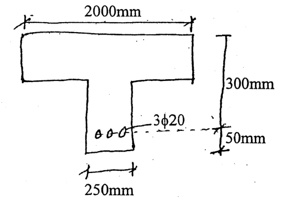
Original 2067 Ashadh Q5b alternative. Any assumed flange thickness must be labelled. - What is the concept behind the typical flange width in T- and L-beams? Explain with necessary sketches. [2+2] (2082 Bhadra, Q2a)
- Describe the design steps of flanged beam sections. [4] (2081 Baishakh, Q2b)
- Explain the design steps of flanged beams. [5] (2078 Bhadra, Q3c)
- Explain how you would design shear reinforcement for flanged beam sections. [5] (2074 Chaitra, Q1a) → also 5.1
- Determine the limiting moment of resistance and limiting area of steel for a RC T-beam of effective flange width 1500 mm, effective depth 590 mm, flange depth 150 mm and web width 240 mm. Use M20 concrete and Fe415 steel. [6] (2081 Baishakh, Q2c)
- A T-beam has an effective flange width of 1600 mm, flange thickness of 110 mm, web breadth of 300 mm and overall depth of 460 mm. It is reinforced with 4 tension bars of 20 mm diameter at an effective cover of 40 mm. Determine the moment of resistance of the section using the limit state method. Use M20 concrete and Fe415 steel. [8] (2076 Ashwin, Q1b)
- An L-beam has an effective flange width of 925 mm, an effective depth of 450 mm, a flange thickness of 100 mm and a rib breadth of 250 mm. It is reinforced with 4 bars of 20 mm diameter in tension and 3 bars of 16 mm diameter in compression. Find the ultimate moment of resistance of the section at the limit state of collapse. Use M20 concrete and Fe415 steel. [10] (2074 Chaitra, Q4b)
- An L-beam has a flange of effective width 900 mm and depth 100 mm; the web below is 250 mm × 500 mm. Determine the reinforcement required if it has to carry a factored bending moment of 615 kN-m and a shear force of 50 kN. Adopt M20 concrete and Fe500 steel. [14] (2072 Kartik, Q4b)
- A beam is simply supported on two walls, each 250 mm thick, with a clear span of 6 m. It has to support a slab 150 mm thick and a live load of 3 kN/m². The beams are spaced at 4 m centre to centre. Design one of the T-beams using M20 concrete and Fe415 steel. Design for shear is not required. [13] (2065 Shrawan, Q2b)
- A floor consists of a 125 mm thick RC slab integrally connected with the beams as shown in the figure. Design an intermediate beam for bending moment and deflection if the floor is subjected to live load 4 kN/m² and floor finish 0.7 kN/m². The supplied layout shows four 4 m bays, beams spanning the 5 m direction and one-brick-thick perimeter walls. [10] (2069 Chaitra, Q2a)
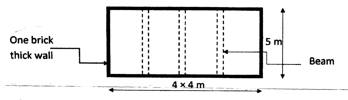
Floor and intermediate-beam layout supplied with 2069 Chaitra Q2a.
Q1. Determine the moment of resistance of the section shown in the figure. Take permissible concrete stress 7 N/mm² and steel stress 140 N/mm². The T-section has flange width 2000 mm, web width 250 mm, effective depth 300 mm, effective bottom cover 50 mm and three 20 mm tension bars. [8] (2067 Ashadh, Q5b; OR alternative) Source limitation: flange thickness is not dimensioned in the supplied figure.
Source limitation. The flange thickness is not dimensioned in the supplied figure, so a unique section resistance cannot be asserted without an assumption. First test the case where the neutral axis lies within the flange.
Use bf = 2000 mm, d = 300 mm, Ast = 3π20²/4 = 942.48 mm², σcbc = 7 MPa, σst = 140 MPa and m = 280/21 = 13.333. The WSM neutral-axis equation bfx²/2 = mAst(d − x) gives x = 55.437 mm. The lever arm is 281.521 mm.
Conditional resistance: if the actual flange thickness is at least 55.437 mm, the compression zone lies within the flange and MR = 140Astz = 37.146 kN·m. The accompanying concrete stress is 2.380 MPa, below 7 MPa.
If the flange is thinner than this neutral-axis depth, use its actual thickness and web width 250 mm to locate the transformed centroid and compression resultant. The conditional value above must not be presented as unconditional when the missing thickness is unknown.
Q2. What is the concept behind the typical flange width in T- and L-beams? Explain with necessary sketches. [2+2] (2082 Bhadra, Q2a)
When a slab is cast monolithically with the beam, a portion of the slab acts as the beam's compression flange — an interior beam becomes a T-beam, an edge beam an L-beam. The compressive stress in the flange is not uniform (it falls off away from the web — “shear lag”), so only a limited effective width bf is assumed to carry the compression at a uniform stress. IS 456 gives:
T-beam: bf = l06 + bw + 6Df · L-beam: bf = l012 + bw + 3Df
where l0 = distance between points of zero moment, bw = web width, Df = flange (slab) thickness; bf must not exceed the actual available slab width (beam spacing).
Q3. Describe the design steps of flanged beam sections. [4] (2081 Baishakh, Q2b)
- Find the effective flange width bf and the factored moment Mu.
- Assume the NA in the flange: xu from 0.36fckbfxu = 0.87fyAst. If xu ≤ Df the section behaves as a rectangular beam of width bf: Mu = 0.87fyAst(d − 0.42xu).
- If xu > Df the NA is in the web — split into a flange couple and a web couple, using the equivalent flange depth yf = min(0.15xu + 0.65Df, Df): Mu = 0.36fckbwxu(d − 0.42xu) + 0.45fck(bf − bw)yf(d − yf/2).
- Find Ast from equilibrium; check Ast,min; design shear on the web; check deflection.
Q4. Explain the design steps of flanged beams. [5] (2078 Bhadra, Q3c)
- Find the effective flange width bf and the factored moment Mu.
- Assume the NA in the flange: xu from 0.36fckbfxu = 0.87fyAst. If xu ≤ Df the section behaves as a rectangular beam of width bf: Mu = 0.87fyAst(d − 0.42xu).
- If xu > Df the NA is in the web — split into a flange couple and a web couple, using the equivalent flange depth yf = min(0.15xu + 0.65Df, Df): Mu = 0.36fckbwxu(d − 0.42xu) + 0.45fck(bf − bw)yf(d − yf/2).
- Find Ast from equilibrium; check Ast,min; design shear on the web; check deflection.
Q5. Explain how you would design shear reinforcement for flanged beam sections. [5] (2074 Chaitra, Q1a)
In a flanged beam the shear is resisted essentially by the web only (the thin flange contributes little). Hence the nominal shear stress uses the web width: τv = Vubw·d. Compute the concrete capacity τc from the web steel ratio pt = 100Ast/(bwd). If τv ≤ τc provide nominal stirrups; if τc < τv ≤ τc,max the excess Vus = Vu − τcbwd is carried by vertical stirrups, spacing sv = 0.87fyAsvdVus (≤ 0.75d, 300 mm). τv must not exceed τc,max.
Q6. Determine the limiting moment of resistance and limiting area of steel for a RC T-beam of effective flange width 1500 mm, effective depth 590 mm, flange depth 150 mm and web width 240 mm. Use M20 concrete and Fe415 steel. [6] (2081 Baishakh, Q2c)
Given: bf = 1500 mm, d = 590 mm, Df = 150 mm, bw = 240 mm, M20, Fe415. Required: Mu,lim and Ast,lim.
Step 1 — Neutral-axis position. xu,max = 0.48 × 590 = 283.2 mm > Df = 150 mm. The neutral axis is in the web, so account for the web and flange-overhang compression separately, using the applicable equivalent flange depth.
Step 2 — Equivalent flange depth. yf = min(0.15xu,max + 0.65Df, Df) = min(0.15 × 283.2 + 0.65 × 150, 150) = 139.98 mm.
Step 3 — Limiting moment (web couple + flange couple). Mu,lim = 0.36fckbwxu,max(d − 0.42xu,max) + 0.45fck(bf − bw)yf(d − yf/2)
= 0.36×20×240×283.2×(590 − 118.9) + 0.45×20×1260×140×(590 − 70) = 230.5 + 825.6 = 1056 kN·m.
Step 4 — Limiting tension steel (from C = T). Ast,lim = 0.36fckbwxu,max + 0.45fck(bf − bw)yf0.87fy = 489370 + 1587600361.1 = 5752 mm².
Answer Using unrounded intermediate values, Mu,lim = 1055.97 kN·m and Ast,lim = 5751.95 mm². These are theoretical limiting-section values; fitting that steel into a 240 mm web needs a separate practical arrangement and depth check.
Q7. A T-beam has an effective flange width of 1600 mm, flange thickness of 110 mm, web breadth of 300 mm and overall depth of 460 mm. It is reinforced with 4 tension bars of 20 mm diameter at an effective cover of 40 mm. Determine the moment of resistance of the section using the limit state method. Use M20 concrete and Fe415 steel. [8] (2076 Ashwin, Q1b)
Given: bf = 1600 mm, Df = 110 mm, bw = 300 mm, D = 460 mm, Ast = 4−20 φ, cover 40, M20, Fe415. Required: M.O.R.
Step 1 — Section properties. d = 460 − 40 = 420 mm; Ast = 4×314.2 = 1257 mm².
Step 2 — Assume NA in the flange (rectangular beam of width bf). xu = 0.87fyAst0.36fckbf = 0.87×415×12570.36×20×1600 = 39.4 mm.
Step 3 — Verify. xu = 39.4 < Df = 110 ⇒ NA indeed in the flange; the section acts as a rectangular beam bf×d.
Step 4 — Moment of resistance. Mu = 0.87fyAst(d − 0.42xu) = 0.87×415×1257×(420 − 16.5) = 183.1 kN·m.
Answer M.O.R. ≈ 183.1 kN·m (under-reinforced, NA in flange).
Q8. An L-beam has an effective flange width of 925 mm, an effective depth of 450 mm, a flange thickness of 100 mm and a rib breadth of 250 mm. It is reinforced with 4 bars of 20 mm diameter in tension and 3 bars of 16 mm diameter in compression. Find the ultimate moment of resistance of the section at the limit state of collapse. Use M20 concrete and Fe415 steel. [10] (2074 Chaitra, Q4b)
Given: bf = 925 mm, d = 450 mm, Df = 100 mm, bw = 250 mm, Ast = 4−20 φ, Asc = 3−16 φ, d′ = 40 mm, M20, Fe415. Required: ultimate M.O.R.
Step 1 — Steel areas. Ast = 4×314.2 = 1257 mm²; Asc = 3×201.1 = 603 mm².
Step 2 — Compatible stresses. The question does not specify compression cover, so d′ = 40 mm is an assumption. Solve 0.36fckbfxu + (fsc − fcc)Asc = 0.87fyAst. The local concrete strain is below 0.002, so fcc must come from the parabolic branch rather than the full plateau.
Step 3 — Neutral axis. Iteration gives xu approximately 53.063 mm; the compression steel is elastic at this strain. Use its actual stress and the local displaced-concrete stress in the moment equation.
Step 4 — Verify. xu = 53.2 < Df = 100 ⇒ NA in the flange (rectangular bf).
Step 5 — Moment of resistance. MR = 0.36fckbfxu(d − 0.42xu) + (fsc − fcc)Asc(d − d′) = 192.28 kN·m.
Study answer 192.28 kN·m for the stated 40 mm compression-cover assumption.
Q9. An L-beam has a flange of effective width 900 mm and depth 100 mm; the web below is 250 mm × 500 mm. Determine the reinforcement required if it has to carry a factored bending moment of 615 kN-m and a shear force of 50 kN. Adopt M20 concrete and Fe500 steel. [14] (2072 Kartik, Q4b)
Verified geometry: bf = 900 mm, Df = 100 mm and the web below the flange is 250 × 500 mm. Thus D = 600 mm. Adopt effective covers 50 mm, giving d = 550 mm and d′ = 50 mm. Mu = 615 kN·m, Vu = 50 kN, M20/Fe500.
1. Limiting compression block. xu,max = 253 mm and yf = min(0.15 × 253 + 0.65 × 100, 100) = 100 mm. Evaluate the web and flange couples at this axis; additional compression steel is needed for the specified 615 kN·m.
2. Trial reinforcement and equilibrium. Three 36 mm tension bars give 3053.63 mm², and two 25 mm compression bars give 981.75 mm². Using compatible steel stresses and the flange/web concrete forces, the actual neutral axis is 207.55 mm < 253 mm, and resistance is 651.36 kN·m > 615 kN·m.
3. Web shear. τv = 50000/(250 × 550) = 0.364 MPa. The provided longitudinal area gives adequate concrete shear resistance; satisfy minimum transverse steel with two-legged 8 mm stirrups at 250 mm centres, using 415 MPa as the ordinary shear-design strength cap. This is within the ordinary spacing and minimum-steel limits.
Study result Three 36 mm tension bars and two 25 mm compression bars pass the stated section check at d = 550 mm. Verify nominal cover, fit of the large bars, anchorage and actual torsion/support conditions before final detailing.
Q10. A beam is simply supported on two walls, each 250 mm thick, with a clear span of 6 m. It has to support a slab 150 mm thick and a live load of 3 kN/m². The beams are spaced at 4 m centre to centre. Design one of the T-beams using M20 concrete and Fe415 steel. Design for shear is not required. [13] (2065 Shrawan, Q2b)
Given: clear span = 6 m, wall = 250 mm, slab Df = 150 mm, spacing = 4 m c/c, LL = 3 kN/m², M20, Fe415. Assume web 300×500 mm (d = 460 mm). Required: flexural steel.
Step 1 — Slab load (per m²). Assume an additional floor finish of 1.0 kN/m² for this study design; it is not supplied in the question. Slab load = 0.15 × 25 + 1.0 + 3.0 = 7.75 kN/m².
Step 2 — Load on the beam. Tributary width = 4 m ⇒ w = 7.75×4 + web self-wt (0.3×0.35×25 = 2.6) = 33.6 kN/m. Leff = 6 + 0.25 = 6.25 m.
Step 3 — Factored moment. M = 33.6×6.25²8 = 164.2 kN·m ⇒ Mu = 1.5×164.2 = 246.3 kN·m.
Step 4 — Effective flange width (IS 456 Cl 23.1.2). bf = l06 + bw + 6Df = 62506 + 300 + 900 = 2242 mm (< spacing 4000 mm, OK).
Step 5 — Tension steel. Ast = 0.5fckfy[1 − √(1 − 4.6Mufckbfd²)]bfd = 1531 mm² → 5−20 φ (1571 mm²).
Step 6 — Check NA. xu = 0.87fyAst0.36fckbf = 34.2 mm < Df = 150 ⇒ NA in flange, section OK.
Study result Overall beam 300 × 500 mm with the 150 mm slab included in its depth, bf = 2241.67 mm and five 20 mm tension bars. Using exact self-weight gives Mu = 246.28 kN·m; the provided section has xu = 35.14 mm and capacity 252.51 kN·m at the assumed d = 460 mm. Confirm the closely packed single-layer bars fit the cover and aggregate-size requirements.
Q11. A floor consists of a 125 mm thick RC slab integrally connected with the beams as shown in the figure. Design an intermediate beam for bending moment and deflection if the floor is subjected to live load 4 kN/m² and floor finish 0.7 kN/m². The supplied layout shows four 4 m bays, beams spanning the 5 m direction and one-brick-thick perimeter walls. [10] (2069 Chaitra, Q2a)
1. Establish the load path and assumptions. The intermediate beam has a tributary slab width of 4 m and spans the 5 m direction. Assume 230 mm supporting walls for the one-brick wall convention, simply supported ends, M20 concrete, Fe415 steel and a trial beam 250 mm wide by 450 mm overall, including the 125 mm slab. Adopt effective cover 50 mm, so d = 400 mm.
2. Loading. Slab self-weight is 0.125 × 25 = 3.125 kN/m². Including the supplied live load and floor finish gives 3.125 + 4 + 0.7 = 7.825 kN/m². The line load from the slab is 7.825 × 4 = 31.30 kN/m. Add only the web below the slab: 0.25(0.450 − 0.125)25 = 2.03125 kN/m. Total service line load is 33.33125 kN/m.
3. Effective span and moment. L = min(5 + 0.400, 5 + 0.230) = 5.230 m. Thus Mu = 1.5wL²/8 = 170.945 kN·m. Effective flange width bf = L/6 + bw + 6Df = 1871.67 mm, below the 4000 mm available width.
4. Provide and verify steel. Four 22 mm bars provide 1520.53 mm². Their neutral axis is 40.738 mm, inside the 125 mm flange and below the 192 mm code limit. The sectional resistance is 210.202 kN·m, exceeding the design moment. Confirm bar fit and the actual effective cover in the reinforcement drawing.
5. Deflection. L/d = 5230/400 = 13.075. The product of the applicable tension, compression and flanged-section modification factors must therefore be at least 0.654 for the basic simply supported ratio of 20. Read those factors at the provided steel percentage and service stress or calculate deflection explicitly. This remaining chart-dependent step is not assumed to pass. Complete shear and anchorage checks before treating the trial as a finished beam design.